Flex Circuit Manufacturers’ Techniques
As a result of their ability to be bent and folded, flexible circuits have a significant advantage over traditional wire and cable. This can significantly shorten assembly time and reduce the amount of line items on a bill of materials. However, there are several considerations that must be considered when designing a flexible circuit.
One of the most important aspects of flex circuit fabrication is choosing the right conductive material. Conductive materials are the electric paths that connect components on a circuit board and are usually made of copper. Using the wrong type of conductive material can cause the circuit to be less reliable and may even compromise its performance.
Another important factor in flex circuit manufacturer is the layer count. It is recommended that the layer count be kept to a minimum to minimize manufacturing costs. This can be done by using multi-layer boards or by implementing the nesting technique. It is also advisable to use as few bends as possible, especially at the ends of the circuit. This will decrease the number of layers needed to maintain the integrity of the circuit.
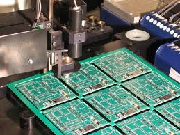
Flex Circuit Manufacturers’ Techniques for Laying Flexible Circuits
Lastly, it is essential to choose the correct design parameters for the flex circuits. The layer count, routing complexity and bend radius are all critical factors in determining how well the flex circuit will perform. Choosing the right conductive material is also critical for flex circuits, as it will directly impact the electrical performance of the final product.
A flex circuit coverlay is used to encapsulate the external circuitry on a flex circuit. It functions similarly to a solder mask on a traditional PCB but with the added capability of flexibility. Typically, the coverlay is made of a polyimide and an attached adhesive, but other thicknesses are available depending on customer requirements.
When laying the circuit, it is necessary to keep the traces perpendicular to the bend area, to avoid stress concentration. This will minimize the possibility of copper breakage. It is also advisable to avoid sharp corners in the flexible areas, as they will create weak points that can fail over time. Instead, rounded corners should be used to prevent stress concentration and failure.
The hole diameters for a flex circuit should be bigger than those on a traditional PCB to allow the proper placement of components and to ensure that they can withstand repeated bending. The plated through holes should also be placed away from the bend area to avoid stress on the copper.
A flex circuit is a good option for electronic products that require a high degree of flexibility and/or ruggedness. In addition, a flex circuit can save space in a portable device by eliminating the need for wires or cables. It is also much lighter than a hard circuit board and can handle a wide temperature range. This makes it a suitable choice for many applications, from consumer electronics to industrial equipment and military systems.